

| Model | Cylinder speed (r/min) |
Balls load (t) |
Feeding size (mm) |
Discharge size (mm) |
Capacity (t/h) |
Motor Power (kw) |
Weight (t) |
| Φ1200×2400 | 36 | 3 | ≤25 | 0.075-0.6 | 2.2-4.8 | 30 | 10.5 |
| Φ1200×3000 | 36 | 3.5 | ≤25 | 0.075-0.4 | 2.7-5 | 37 | 11.8 |
| Φ1200×4500 | 32.4 | 5 | ≤25 | 0.075-0.4 | 4-7.5 | 55 | 13.8 |
| Φ1500×3000 | 29.7 | 7.5 | ≤25 | 0.075-0.4 | 4.3-8 | 75 | 15 |
| Φ1500×3500 | 29.7 | 7.5 | ≤25 | 0.075-0.4 | 4.5-9 | 75 | 16.5 |
| Φ1500×4500 | 27 | 11 | ≤25 | 0.075-0.4 | 6-12 | 90 | 18 |
| Φ1500×5700 | 28 | 12 | ≤25 | 0.075-0.4 | 7-15 | 130 | 22 |
| Φ1830×3000 | 25.4 | 11 | ≤25 | 0.075-0.4 | 6.5-12 | 130 | 28 |
| Φ1830×3600 | 25.4 | 13 | ≤25 | 0.075-0.4 | 8-13 | 130 | 30 |
| Φ1830×4500 | 25.4 | 15 | ≤25 | 0.075-0.4 | 10-18 | 155 | 32 |
| Φ1830×6500 | 24.1 | 21 | ≤25 | 0.075-0.4 | 14-26 | 210 | 35 |
| Φ2100×3000 | 23.7 | 15 | ≤25 | 0.075-0.4 | 9-16 | 180 | 37 |
| Φ2100×3600 | 23.7 | 18 | ≤25 | 0.075-0.4 | 10-19 | 210 | 39 |
| Φ2100×4500 | 23.7 | 24 | ≤25 | 0.075-0.4 | 13-24 | 245 | 41 |
| Φ2200×4500 | 21.5 | 27 | ≤25 | 0.075-0.4 | 14-26 | 280 | 50 |
| Φ2400×3600 | 21 | 23 | ≤25 | 0.075-0.4 | 14-25 | 320 | 63 |
| Φ2400×4500 | 21 | 27 | ≤25 | 0.075-0.4 | 17-32 | 380 | 69 |
| Φ2700×3600 | 20.7 | 33 | ≤25 | 0.075-0.4 | 19-32 | 380 | 90 |
| Φ2700×4000 | 20.7 | 35 | ≤25 | 0.075-0.4 | 20-36 | 380 | 94 |
| Φ2700×4500 | 20.7 | 38 | ≤25 | 0.075-0.4 | 21-40 | 480 | 98 |
| Φ3200×4500 | 19 | 56 | ≤25 | 0.075-0.4 | 35-68 | 800 | 132 |
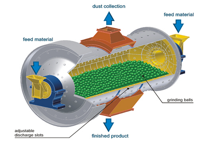
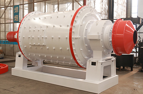
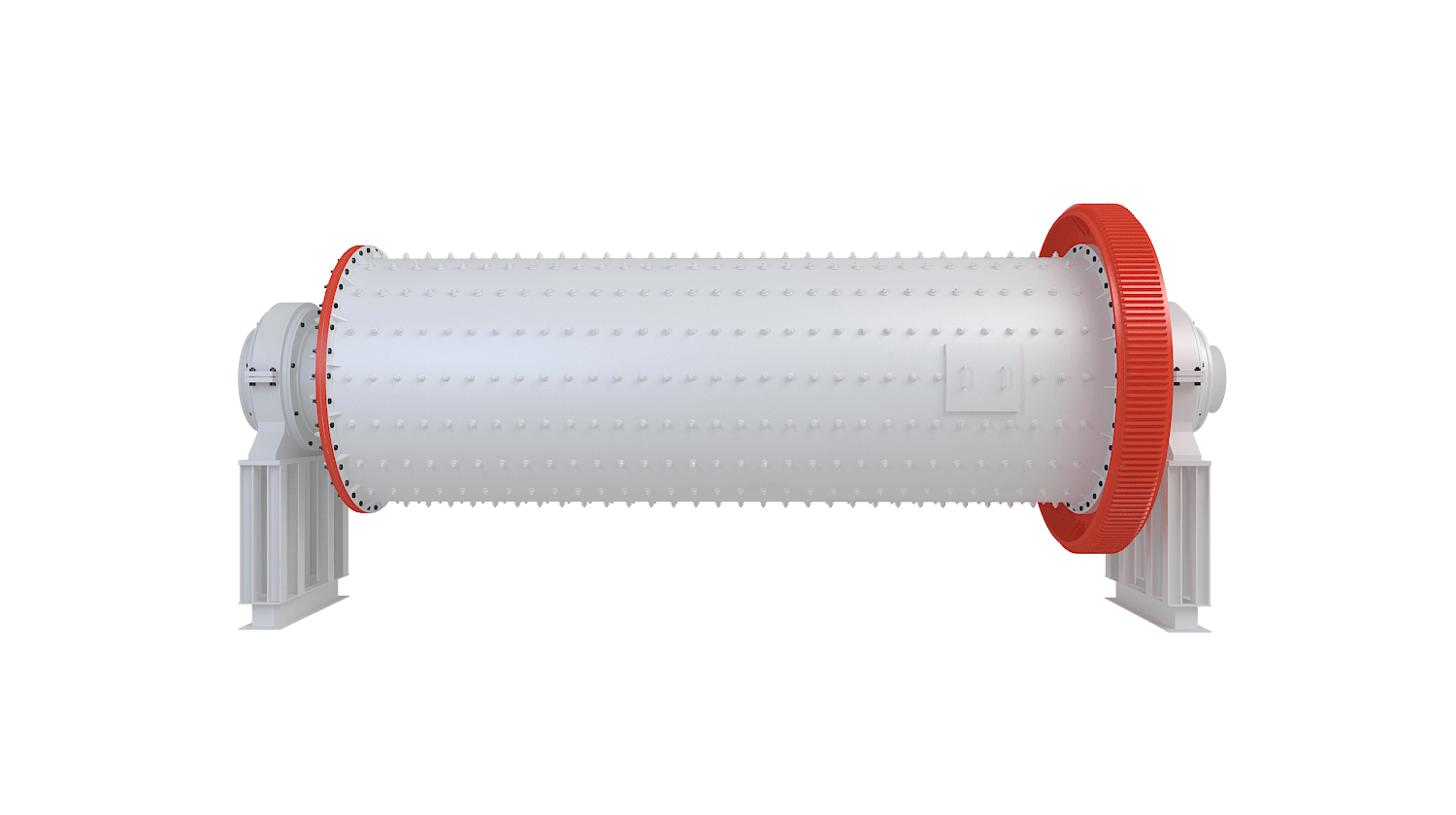
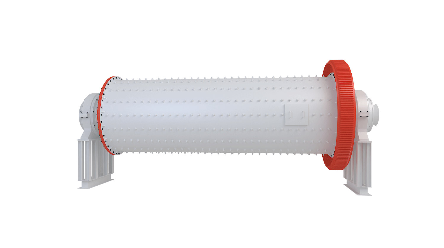
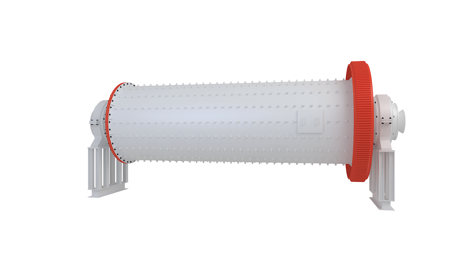
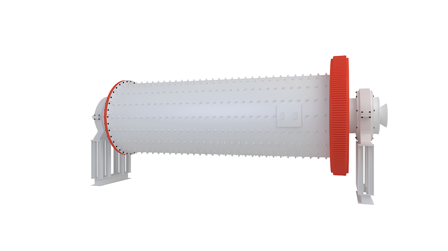
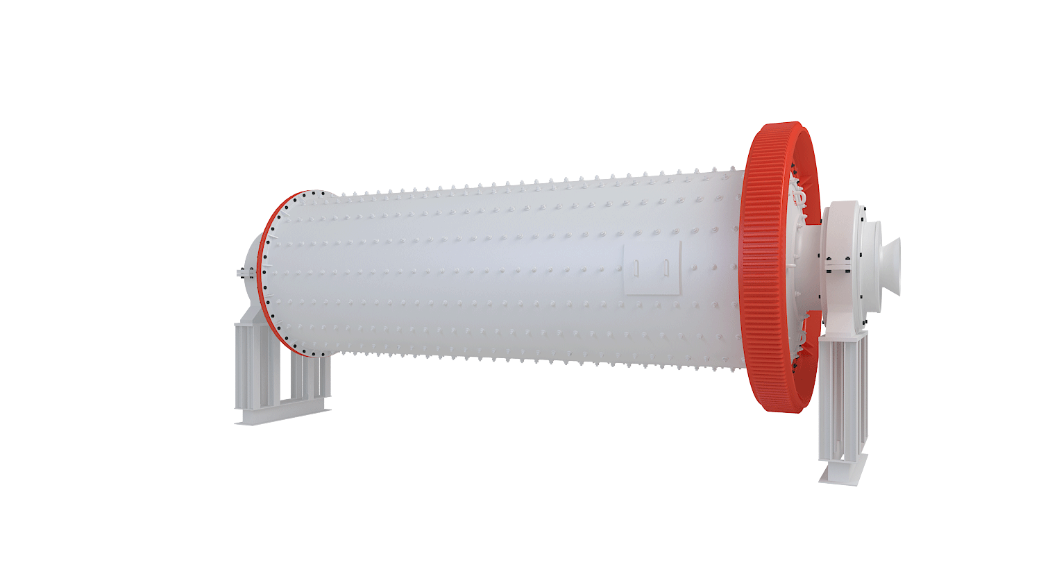
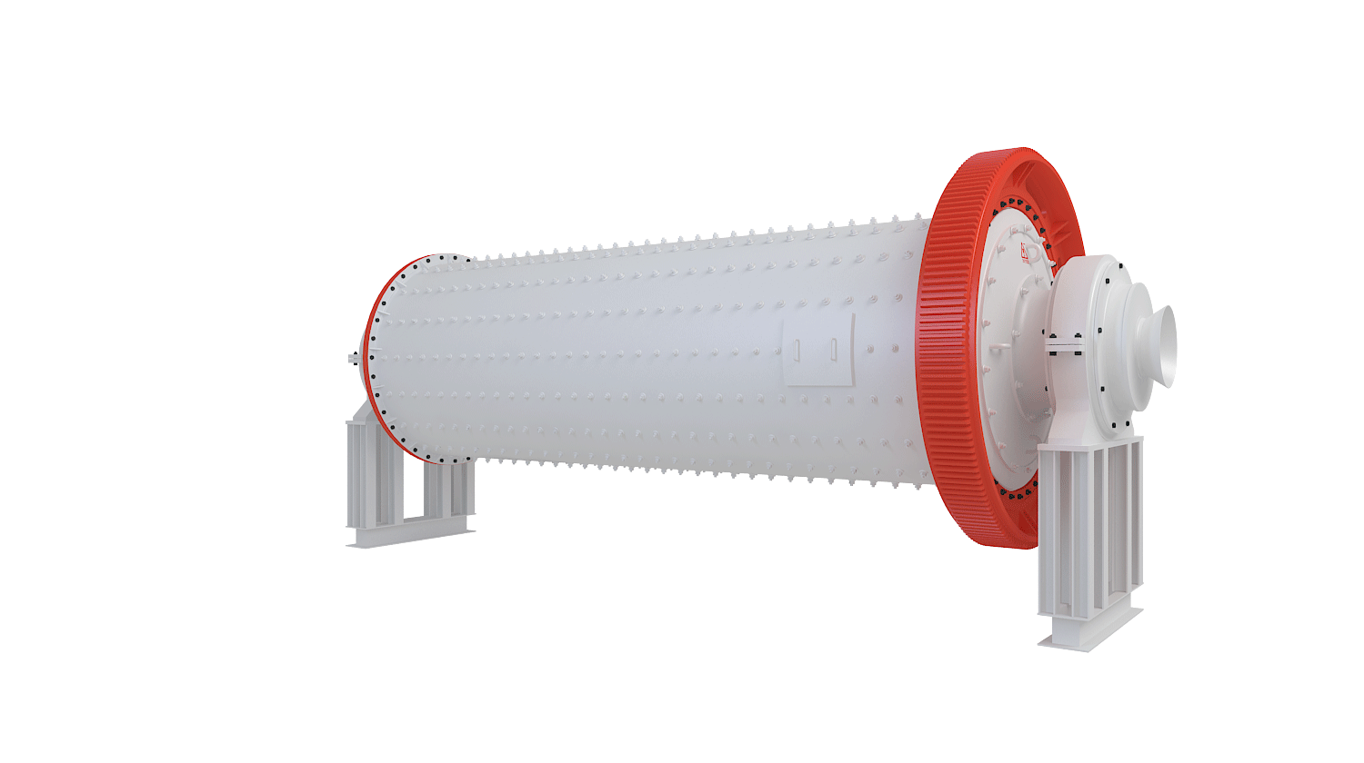
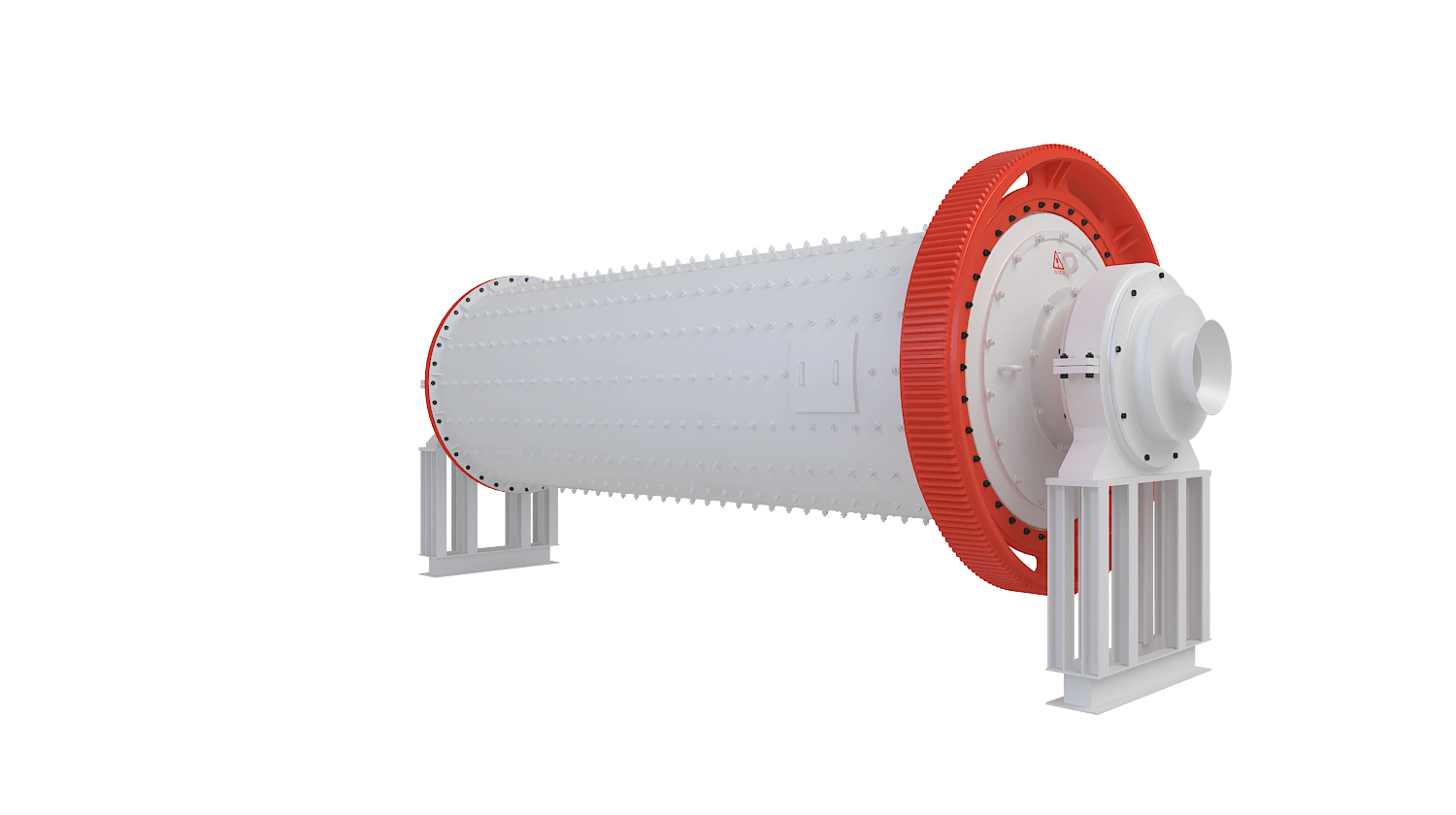
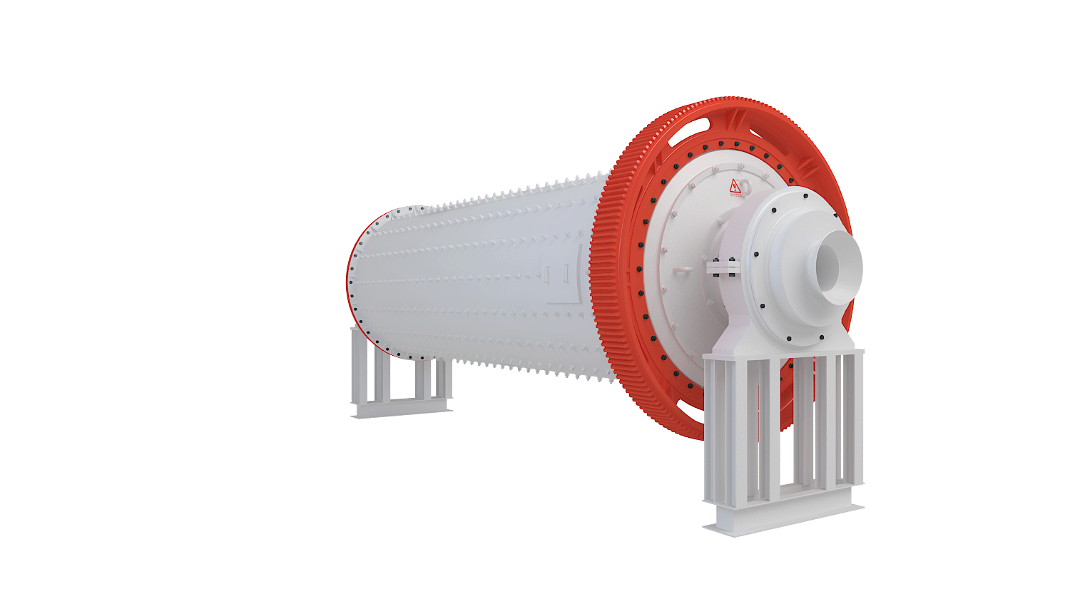
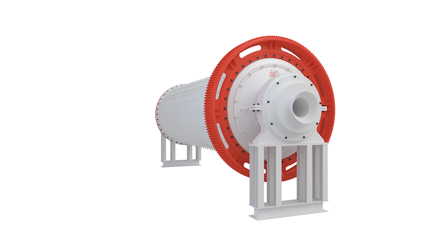
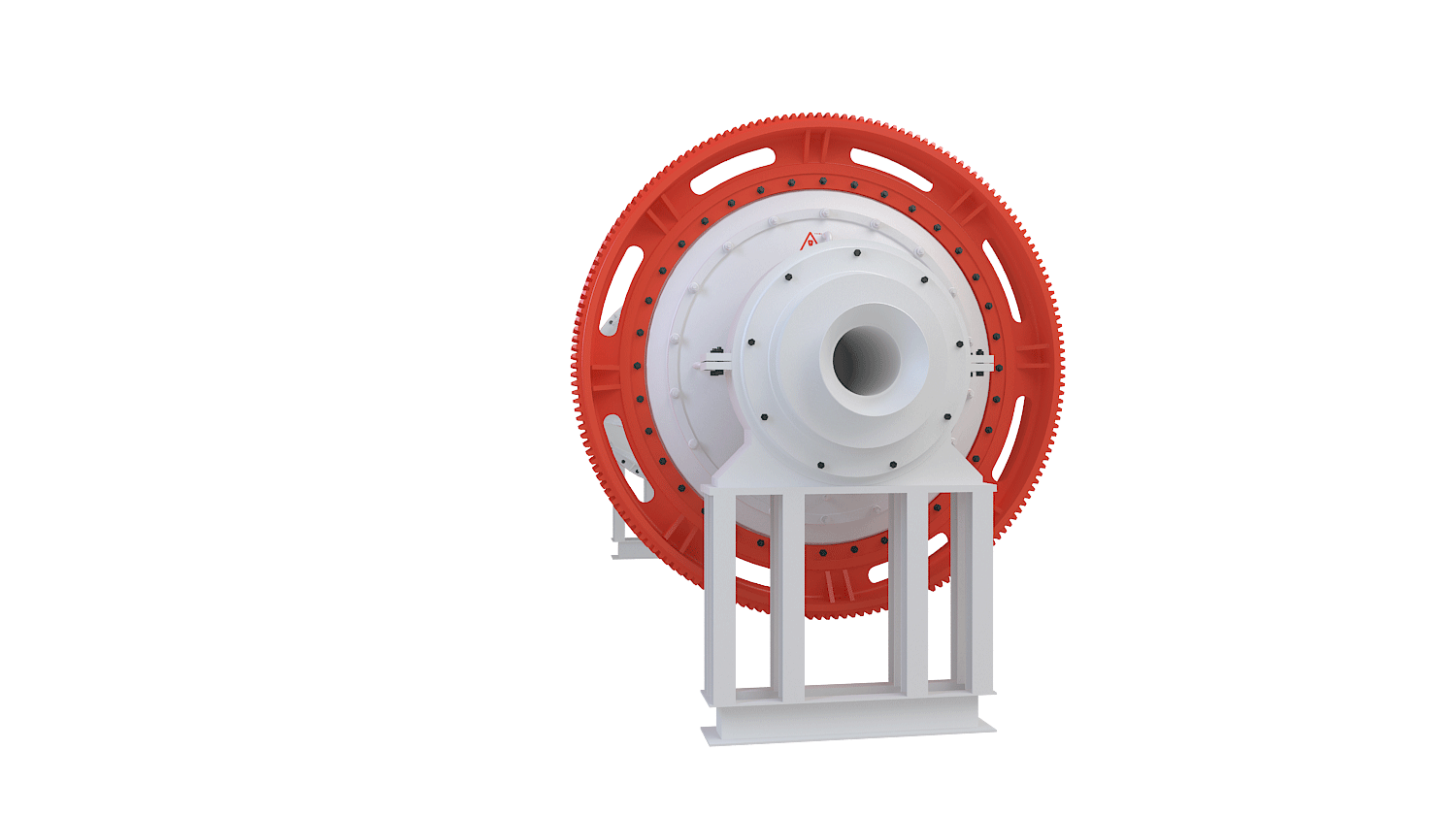
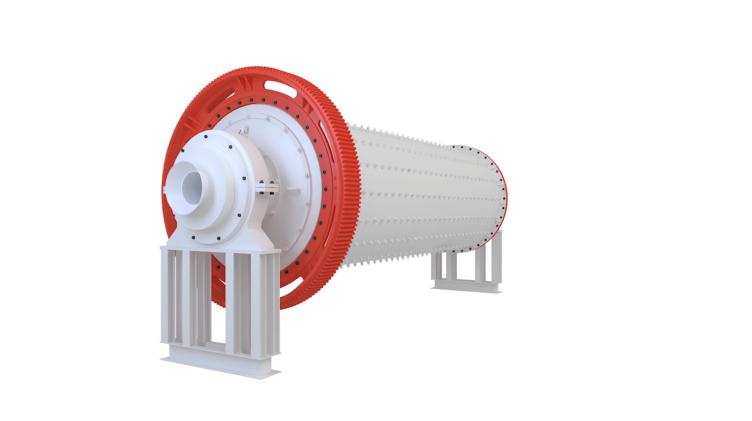
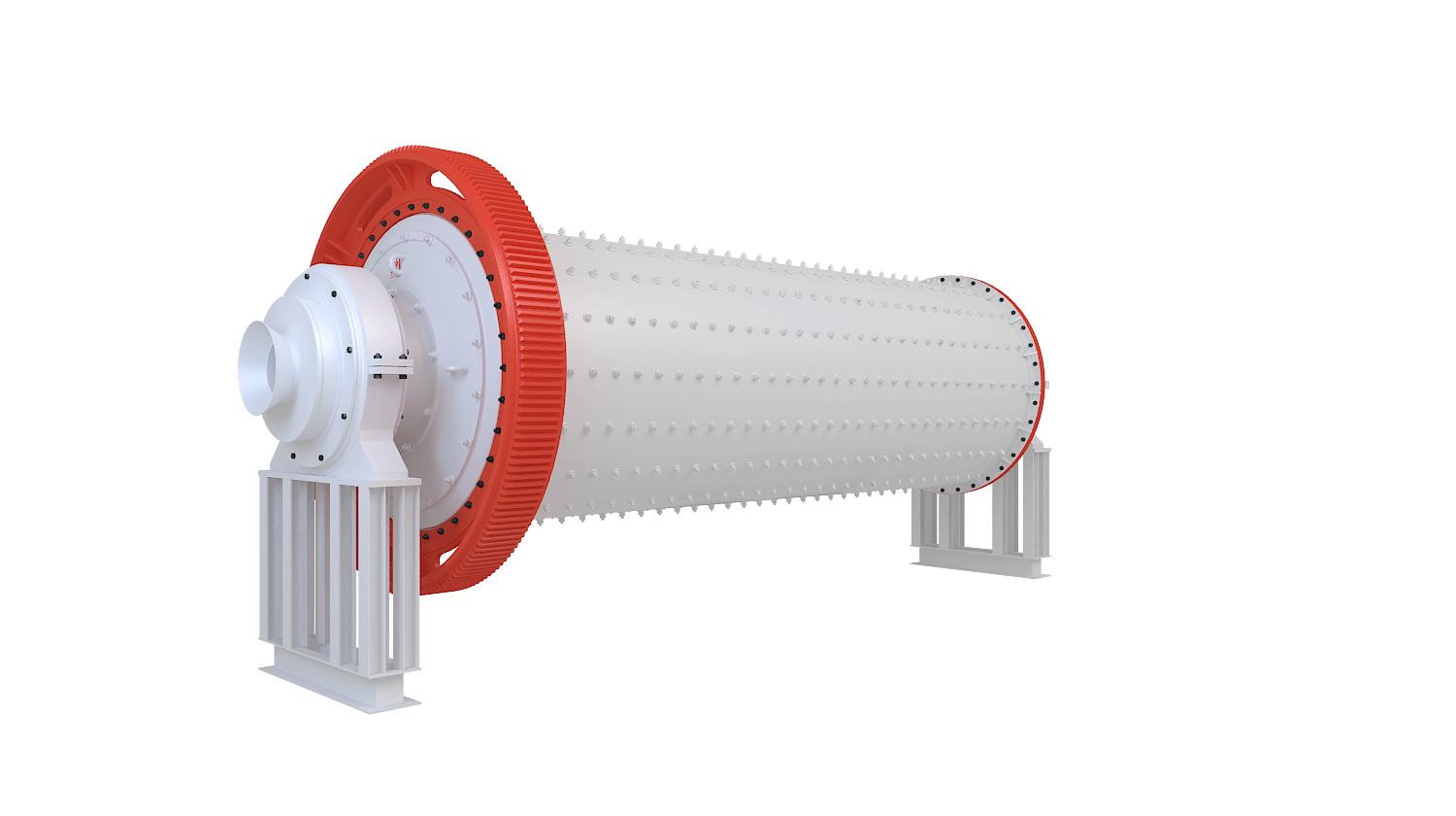
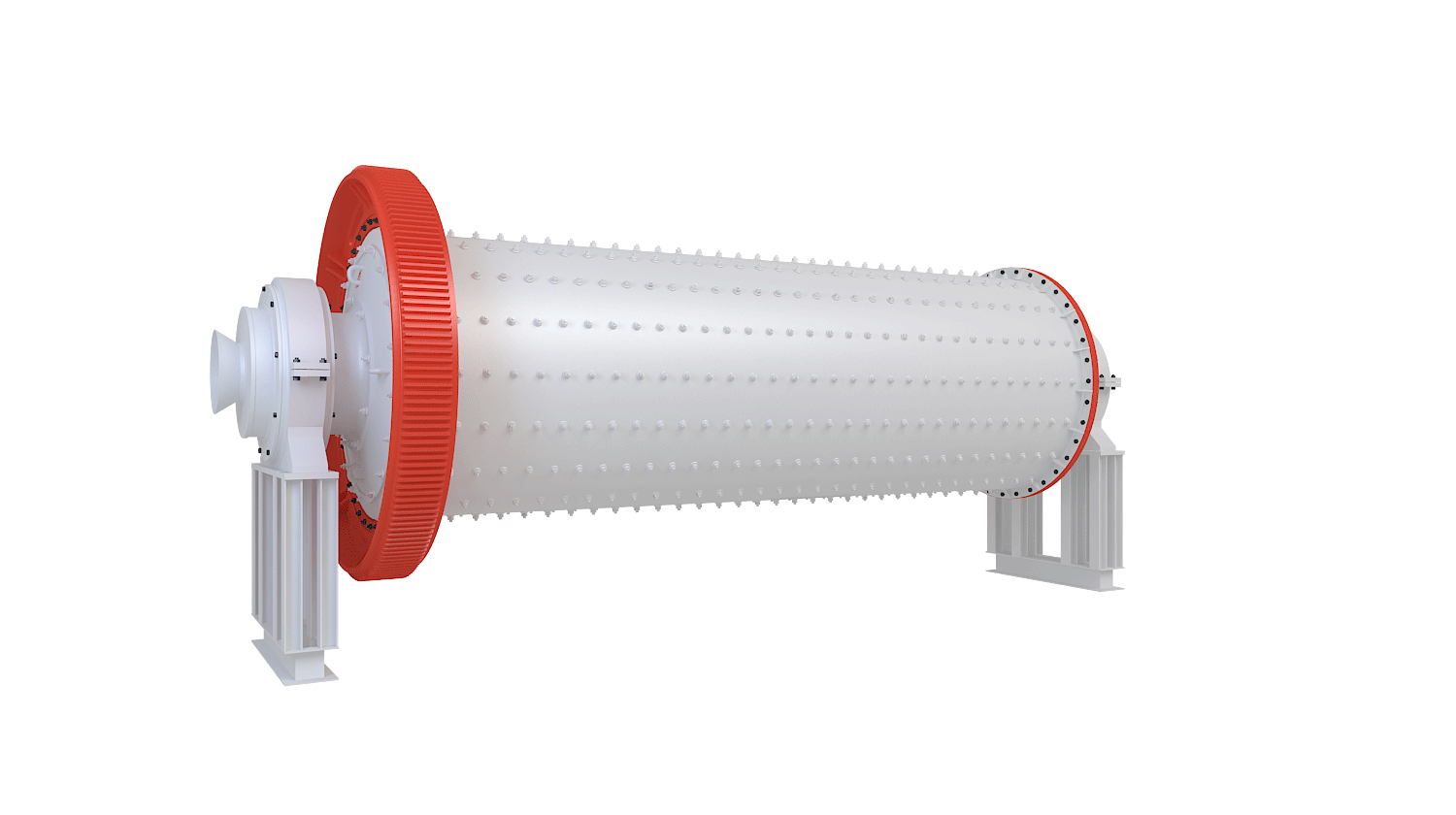
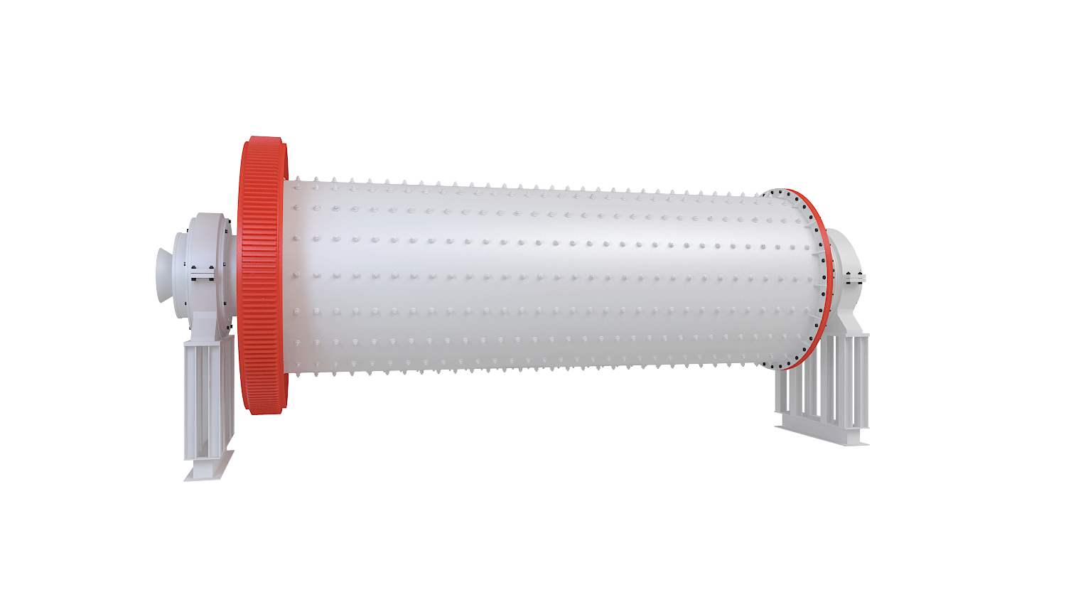
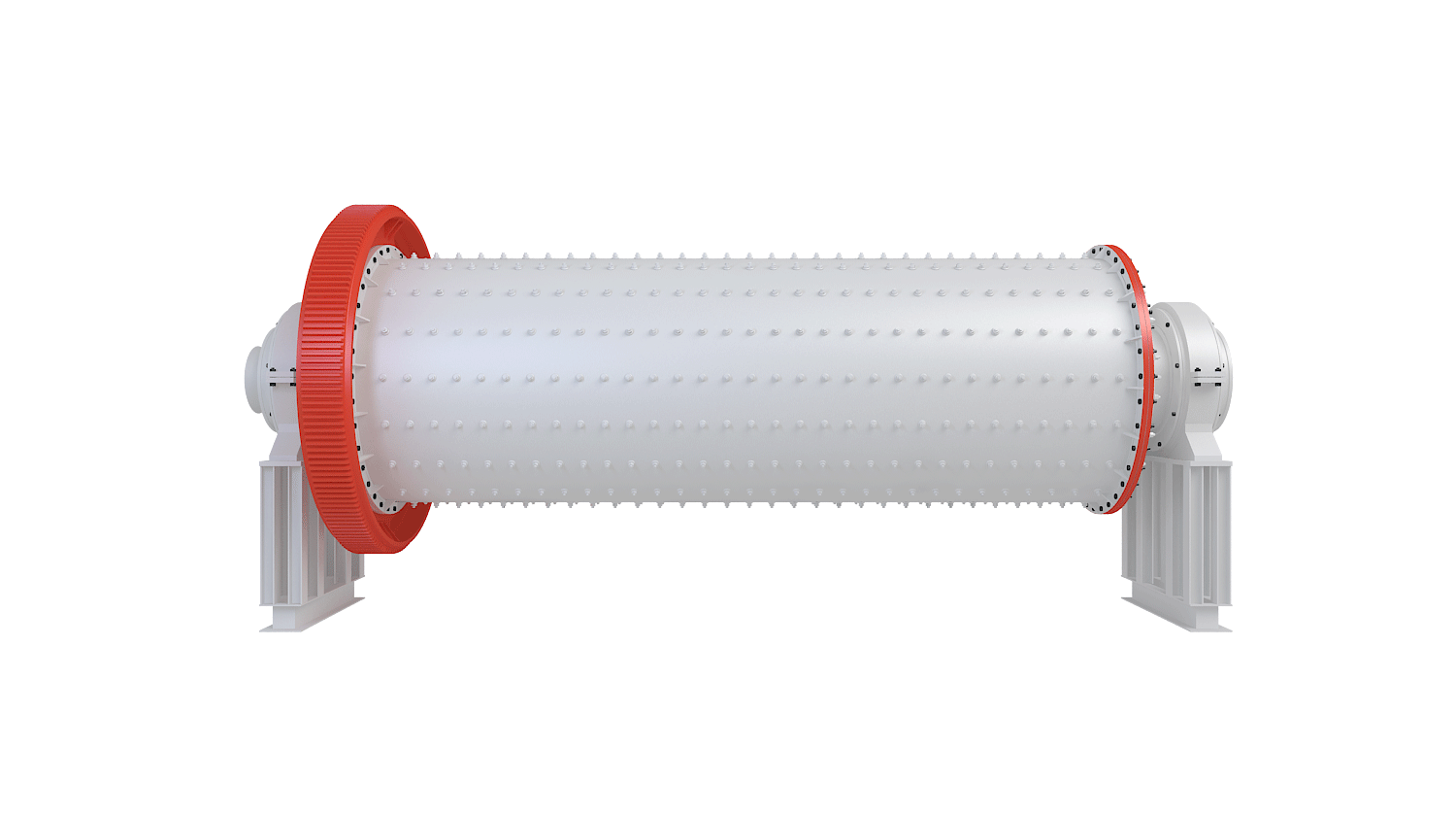
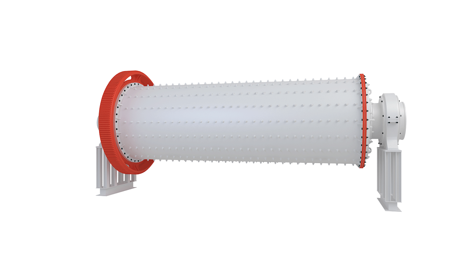
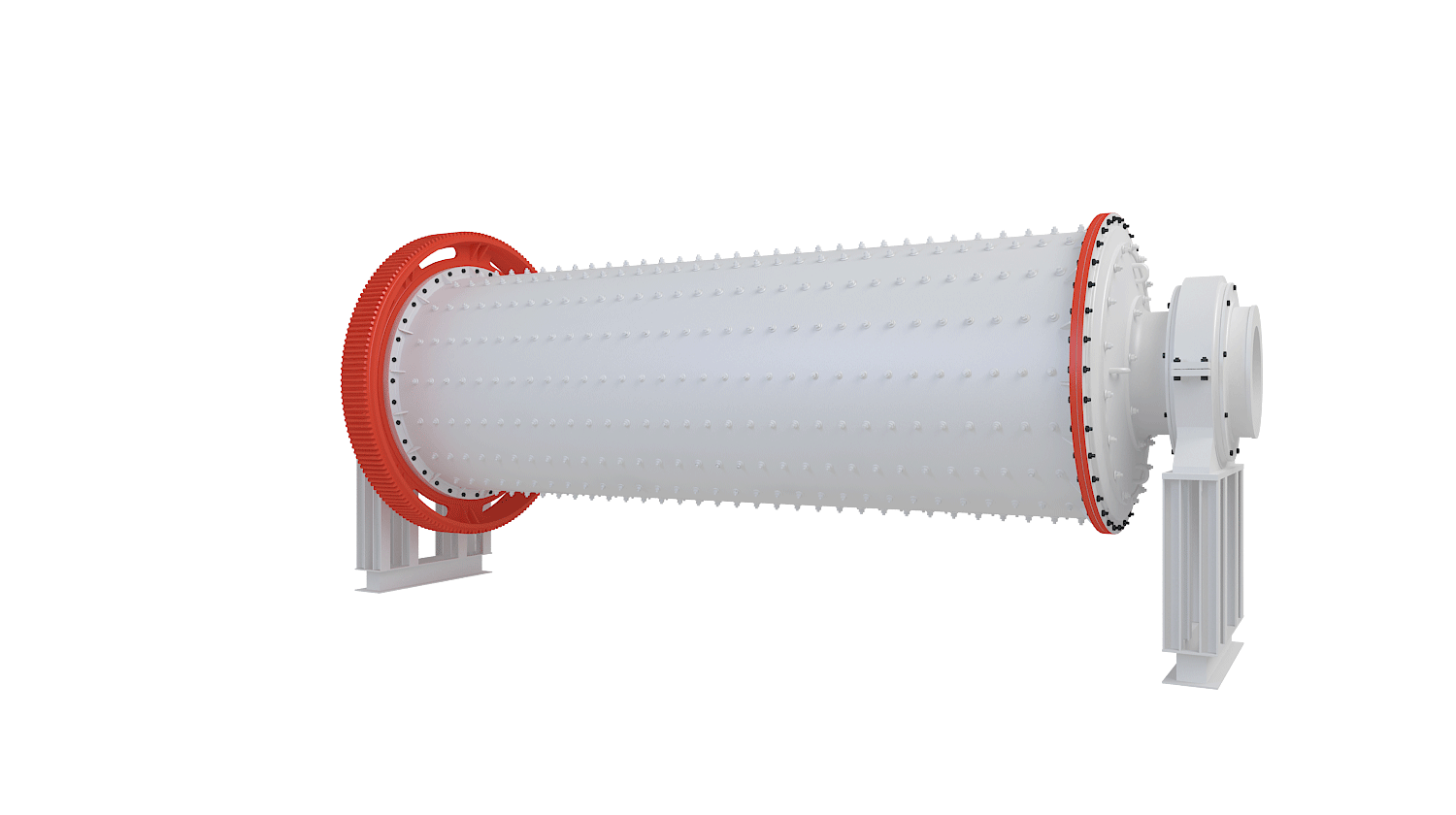
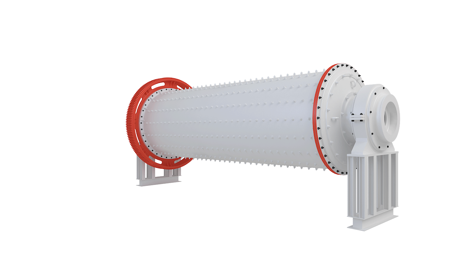
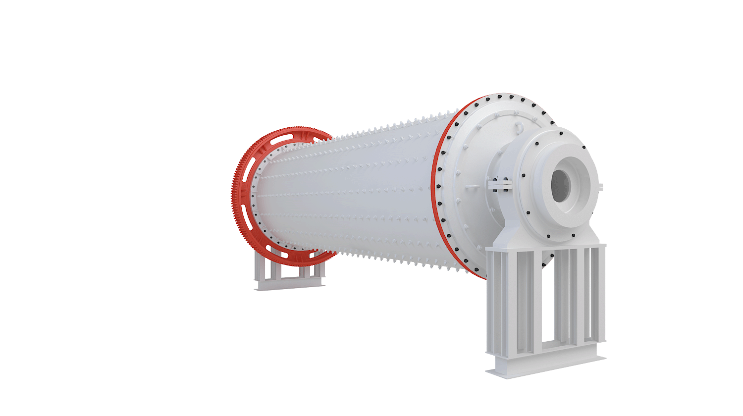
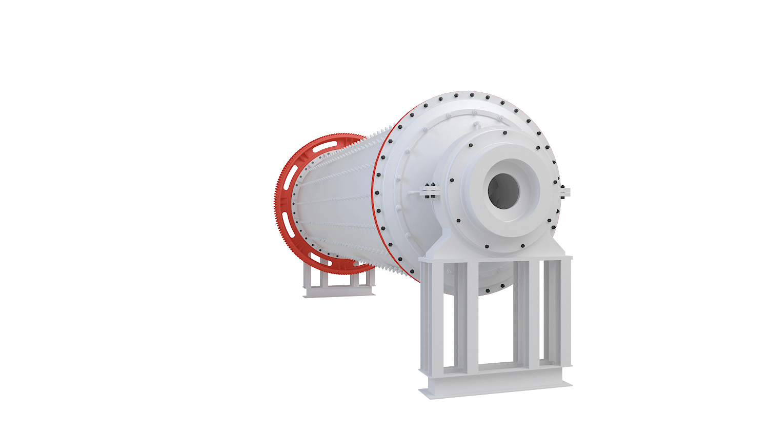
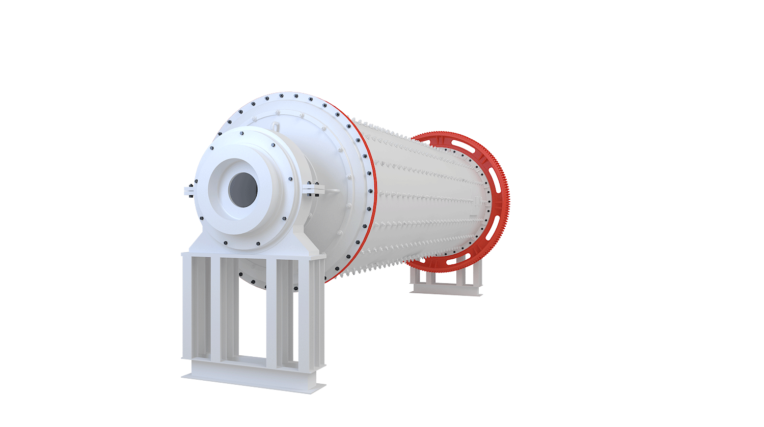
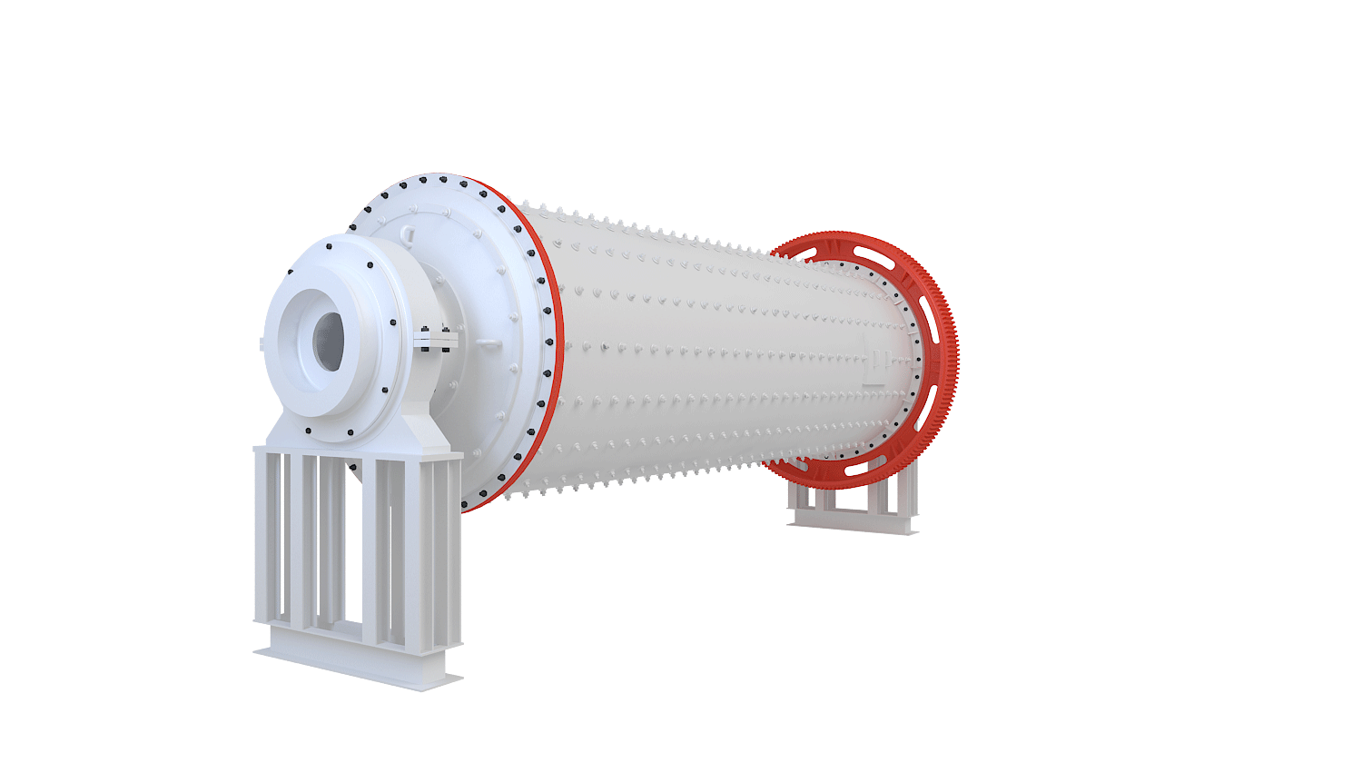
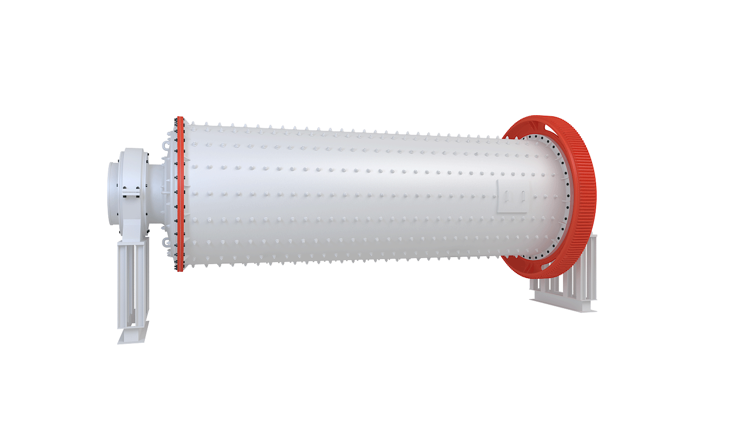
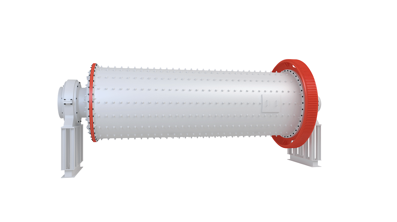
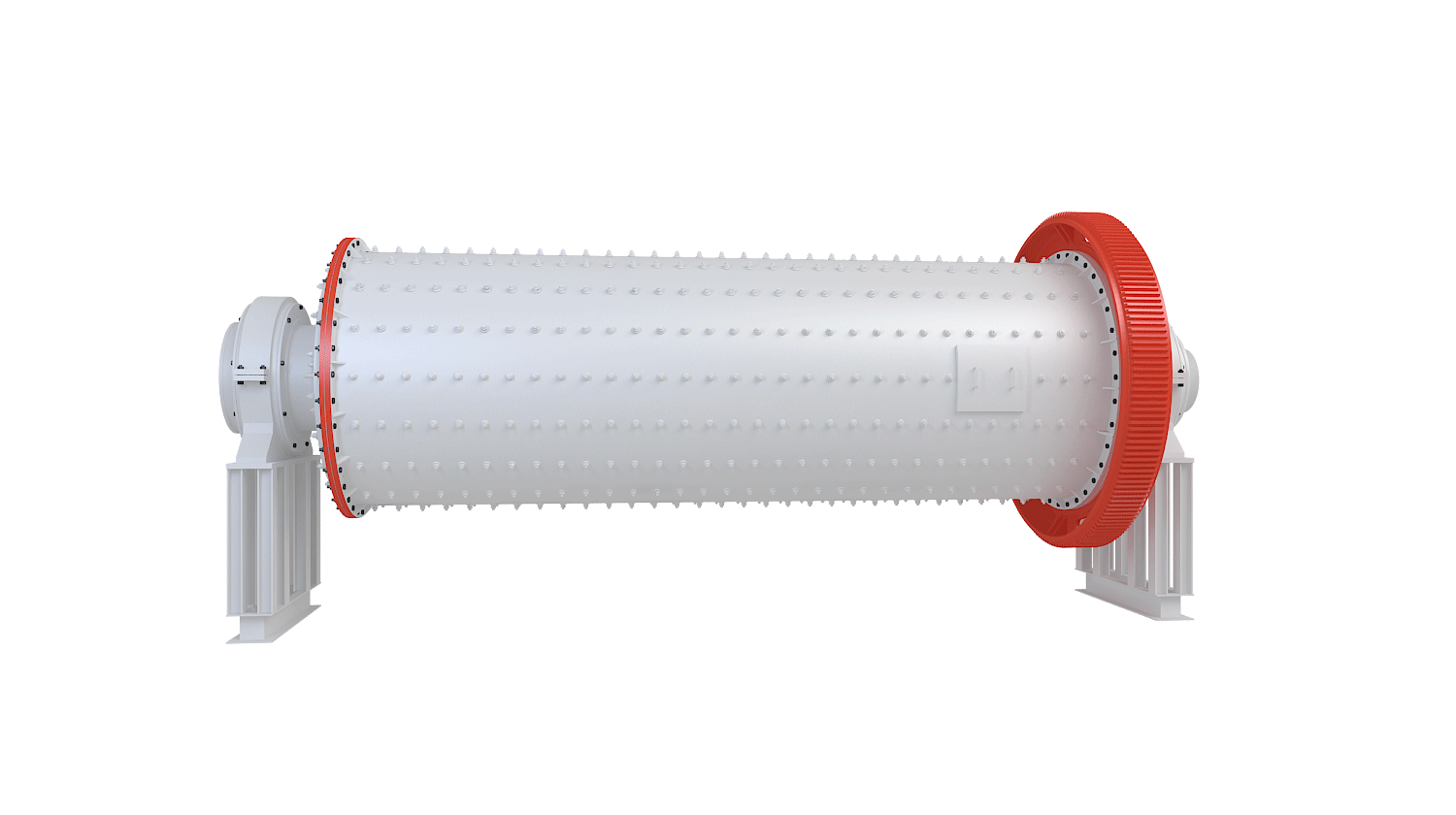
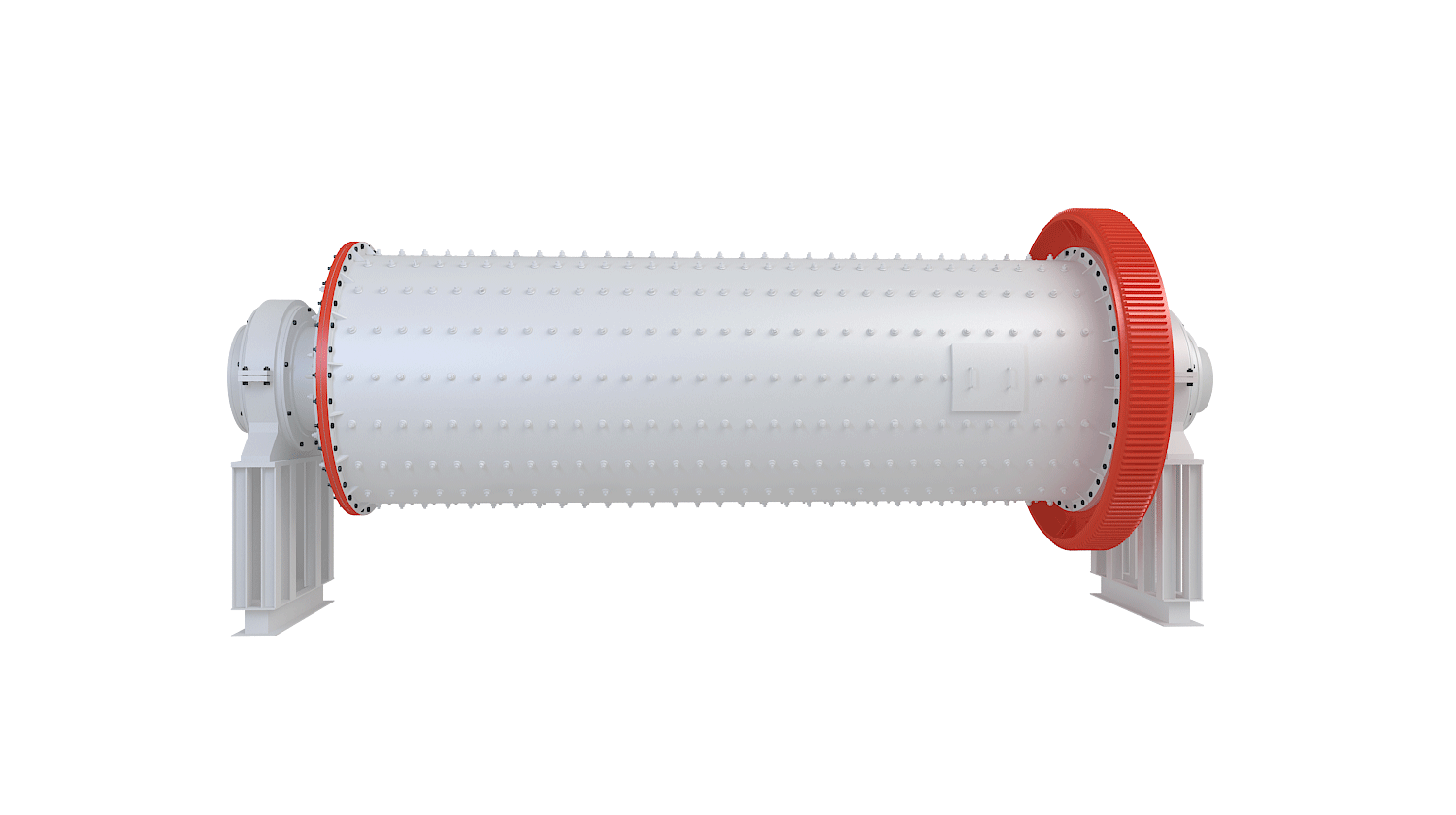
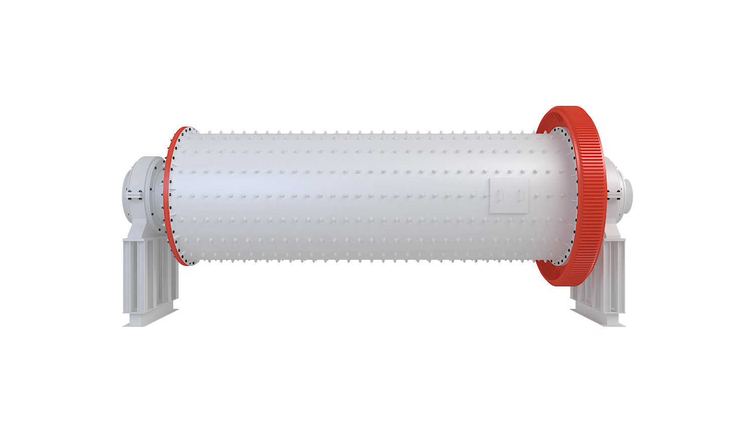
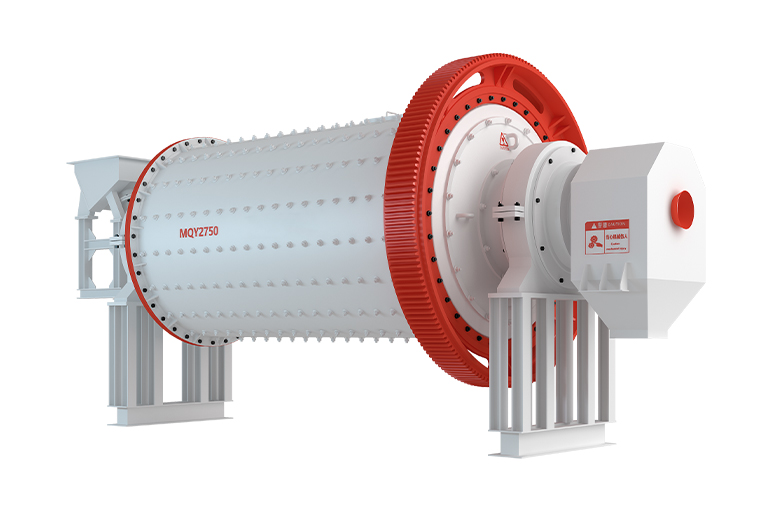
A Ball Mill works on the principle of impact and attrition. As the cylindrical shell rotates around its horizontal axis, the grinding media (usually steel balls) inside the mill are lifted by the lining and then cascade down due to gravity. The material fed into the mill is crushed by the repeated impact and friction caused by the tumbling balls.
The rotation of the drum is typically driven by a motor and transmission system. As the drum rotates, materials and grinding media are lifted along the inner wall and then fall back freely, thus reducing particle size through grinding and impact.